The herebelow page is now obsolete.
Described boards have been modified and the revisions are on the site CNCLoisirs on the page Cartes à réaliser, but only in french. I will no longer translate the page to english. On the CNCLoisirs ('Hobby CNC') site, the licence have been modified and you can now find the boards 'eagle' files if you wish to do modifications. This new licence (cc by-nc-sa) do allow you to copy on any site and translate in any language provided the licence is respected - no commercial use, give credit and distribute under the same licence -.
An important modification is that the L6208 board is now with single face.
Stepper power board based upon L6208 circuit
:
Find herebelow my own
design for stepper command board based upon L6208 circuit.
Stepper bipolar command (4 wires)
Maximum current 2.5A per phase
Mode : 1/2 step
Bridge control : 'Slow decay' (see datasheets)
Command Step/direction
Power supply unstabilised, but rectified and filtered, maximum 32V
Power supply stabilised, maximum 40V.
Forced blow on circuit required.
Board presented here is slightly different from prototype, i've locked it in half-step and control mode in 'Slow
decay'. I've improve design and distance between wires.
This board don't have been tested at maximum current (only tested at 2A), nor
in intensive service.
While integrated circuit accept a maximum current of 2.8A, i've limited the
board to 2.5A.
I've tested without cooling, heating is intense (~100°C), and circuit disjunct
over 1.8A. With a small blower, temperature remains very reasonnable (< 50°C)
For reasons i don't really understand, this board work better than the board
based upon L297/L298 (my machine used both types of boards, in similar conditions).
These are both circuits based upon PWM, but the timing is managed differently.
Circuit cooling is done by printed circuit copper area, so it's imperative that
it will be hot-tinned to improve thermal conductivity, and it might be interesting
to have 70 microns copper thickness.
Circuit L6208 is so welded directly on board and you cannot install a support.
Current adjustment :
You adjust current by adjusting a reference voltage (pin 11 or 24 of IC L6208).
This voltage is measurable on test point noted 'Te' on
the board, which give ground and reference voltage points.
Shunt resistor is 0.25 Ohm (4 resistor of 1 ohm in parallel)
| Current |
0.5 A |
1 A |
1.5 A |
2 A |
2.5 A |
| Voltage |
0.125 V |
0.25 V |
0.375 V |
0.5 V |
0.625 V |
If you use low power steppers, it is preferable to only install 3 resistor instead of 4, so a shunt of 0.333 Ohm.
In that case the table became :
| Current |
0.25 A |
0.5 A |
0.75A |
1 A |
1.5 A |
| Voltage |
0.083 V |
0.166 V |
0.25 V |
0.333V |
0.5 V |
Schematic
 |
 |
Ensemble view |
 |
Copper, Top
Please note the voltage refererence test point 'Te', on left top |
 |
Copper, bottom |
 |
Component view |
 |
Prototype (slightly different from presented model) |
Bill of material
All resistor are carbon, 1/4W except R101-108, 1 Ohm, metal 1/2W, 1%.
Beware, carbon resistors of 1/2W are way too large.
You can install these resistors vertically, with 2 one one side and two on the other side, crossing.
Diode D3 not required if you are certain to not reverse power supply wires.
Attention to weld top and bottom.
Capacitor C12 (470 µF) can be bottom welded only, top/bottom junction
being done on one pin of capacitor C8.
Connectors shall have removable clips, to be welded on top.
For simplification, you can weld directly cables on board.
A high power iron (50-100W) will be used for metal resistor and IC power pin
welding (There is no thermal insulators, as the purpose is cooling)
Circuit L6208 is recent and may be difficult to afford.
| PartValue/Ref |
Device Description,
package |
| C1-C21nF |
Cap. Ceramic, 5mm
|
| C710nF 100V |
Cap. Ceramic, 5mm |
| C8220nF |
Cap. Ceramic, 5mm |
| C12470µF |
Cap. Polarised, radial |
| C18100nF |
Cap. Ceramic, 5mm |
| C21100nF 100V |
Cap. ceramic, 5mm |
| C2447nF |
Cap. ceramic, 5mm |
| D1-D21N4148 |
Diode, 7.5mm |
| D3BYW29 |
Diode, DO220S |
| F1REPSRXE185 |
Polyswitch |
| IC1L6208 |
CI DIL24S Stepper
Controller Driver, STMicroelectronics |
| J1-J2 |
Molex connector male
4pin, 2.5mm |
| R1100 |
Res. carbon, 10mm |
| R24-R25 51k |
Res. carbon, 10mm |
| R30 1k |
Potentiometer 25
rotations S64W |
| R40 6k49 |
Res. carbon, 10mm |
| R44 4.7k |
Res. carbon, 10mm |
| R101-R1081 |
Res. metal 1/2 W,
10mm, 1% |
X1
|
Connector 2 -- 5mm |
If you intend to realize this board, it is imperative that you have experience
in electronic and basic knowledge of repair. This is a double-sided board, so
weld on both side. One oblivion can block working, and even burn the board.
I don't give any support, and schematics are supplied 'as is', without
guaranty of any kind.
Before setting the power, triple check everything.
Use is restricted to personal use only, excluding any commercial use. Diffusion
of the documents is forbidden, everyone must get the informations from Otocoup
Internet site to upload last version.
Beware to never shutdown the signal power supply
(+ 5V) before the stepper power supply, that will destroy power
circuits.
Datasheet
Circuit L6208
Application
note
Application
note for microstepping
Documents
for realisation of power board based on L6208 (Printed circuit, BOM), plus documents
about control board
Images are in 600 dpi
If you are in Europe, company ATEXA www.atexa.fr propose following ensembles :
Printed board drilled and hot-tinned, no components:
. Elecoup 3D : 1 command board, 3 boards for L6208, ask price with shipping
. Elecoup 4D : 1 command board, 4 boards for L6208, ask price with shipping
Price is below 50 Euros for Elecoup 3D,
Expedition by letter within 24/72 hours after reception of payment.
Please note that i have no link with Atexa company and that i don't get any royalty.
Stepper power board
based upon L297/L298 - Specifications :
Find herebelow my own design for stepper command board based upon L297/L298
circuits.
Stepper bipolar command (4 wires)
Maximum current 2A per phase
Mode : 1/2 step
Command Step/direction
Power supply unstabilised, but rectified and filtered, maximum 28V
Power supply stabilised, maximum 38V.
Large radiators and proper ventilation required in your box.
This is a simple face board, more simple to realise than previous model, and
much more classical.
There is no wire between pins of any circuit. This does cost 5 straps,
but is much safer.
Board presented here is slightly different from prototype, i've locked it in
half-step. I've improve design and distance
between wires.
This board have not been tested
in intensive service.
Current adjustment :
You adjust current by adjusting a reference voltage (pin 11 or 24 of IC L6208).
This voltage is measurable on test point on
the board, which give ground and reference voltage points.
Shunt resistor is 0.333 Ohm (3 resistor of 1 ohm in parallel)
| Current |
0.25 A |
0.5 A |
0.75A |
1 A |
1.5 A |
2A |
| Voltage |
0.083 V |
0.166 V |
0.25 V |
0.333V |
0.5 V |
0.66V |
Schematics
Bill of material
All resistor are carbon, 1/4W
except R101-103 and R105-107, 1 Ohm, metal 1/2W, 1%
Diode D9 not required if you are certain to not reverse power supply wires.
| Comp.Value/Ref. |
Description, package |
C1
3.3nF |
Cap. ceramic,
5mm |
| C2100nF |
Cap. ceramic,
5mm |
| C12 470µF |
Cap. polarised,
radial |
C21
100nF |
Cap. ceramic,
5mm |
| C24 10nF |
Cap. ceramic,
5mm |
| D1-D8BYV27 |
Diode, 7.5mm |
| D9 BYW29-100 |
Diode, DO220S |
| F1REPSRXE160 |
Polyswitch 3.2 A |
IC2
L297 |
CI L297 Stepper controller,
STMicroelectronics |
| IC3L298 |
CI L298 double H-bridge,
STMicroelectronics |
JP1
|
jumper 3 pins |
| JP3 |
jumper 3 pins |
J1
|
Molex connector
male 5pin, 2.5mm |
| J2 |
Molex connector
male 4pin, 2.5mm |
| R1 22k |
Res. carbone, 10mm |
| R30 1k |
Potentiometer
S64W |
| R406k49 |
Res. carbone, 10mm |
| R444.7k |
Res. carbone, 10mm |
| R101-R1031 |
Res. metal
1/2 W, 1%, 10mm |
| R105-R1071 |
Res. metal
1/2 W, 1%, 10mm |
X1
|
Terminals 2 wires
-- 5mm |
If you intend to realize this board, it is imperative that you have experience
in electronic and basic knowledge of repair. I
don't give any support, and schematics are supplied 'as is', without guaranty
of any kind.
Before setting the power, triple check everything.
Use is restricted to personal use only, excluding any commercial use. Diffusion
of the documents is forbidden, everyone must get the informations from Otocoup Internet
site to upload last version.
Beware
to never shutdown the signal power supply (+ 5V) before
the stepper power supply, that will destroy power circuits.
Find here the
FILE
for realisation of power board based upon L297/L298 circuits (Printed circuit,
BOM)
Printed circuit image is in 300 dpi, which should be set in your image viewer to print at appropriate scale.
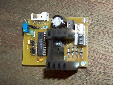
Control board
For being able to control power board as the one presented hereabove (or
another one), Franck Aguerre have designed and built a simple control board
simple, shown herebelow.
| Comp.Value/Ref. |
Description, package |
| IC174LS541 |
Bus drivers |
| IC2NE555 |
Frequency generator |
| IC37805 |
Voltage regulator |
| IC47812 |
Voltage regulator |
| R133 k |
Resistance
1/4W |
| R2 (4x)1k |
Resistance
1/4W |
| P11 M |
Trimmer 25 rotations |
| C11µF |
Capacitor
chemical radial 25-63V - pitch 5mm |
| C2 (2x)10nF |
Capacitor polyester
LCC milfeuil pitch 5 mm |
| C3470 pF |
Capacitor ceramic
pitch 5mm |
| - |
Connector DB25
male angled, to weld |
| Weld pins
pitch 2.54 mm |
| - |
Switch or emergency
shutdown button, pin 19 and 20 of IC1 |
This board is fairly simple, one layer only, but the essential is present :
Control of 4 stepper power boards with signal command isolation, 3 inputs for
end-switches, voltage regulator 12 V and 5V.
Supreme luxury, there is a frequency generator at 2 kHz, to be used for hotwire
cutting. (With Gilles Muller software, this frequency generator is used to
stabilised output of steps, which tend to be ubstable under Windows (tm)).If your power supply exceed 14V, it is needed to install a 12V regulator before the 5V regulator.
If not needed, shunt the circuit. Beware, under 14V, the 12V voltage regulator
is unable to work.Fan power supply will be installed downstream the 12V regulator.Beware to adpt the input
capacitor voltage to your power supply (20% voltage over
the operating voltage).
If not, you risk an explosion, and it is said to be very noisy.For Otocoup machine,
it is needed to have an emergency shutdown which cut step signals, without
cutting power on steppers. For that, there is on the circuit 2 pins which
much be linked to have the 74 LS 541 driver conducting.Emergency shutdown cut
the driver, and so step and dir signals, but you have to, on Otocoup machine,
left power supply on stepper power boards to maintain the carriage in place.On an horizontal machine, there is no problem to totally cut steppers power supply.Attention, in all cases, emergency shutdown must shut the router
This control board is compatible with hotwire software
of Gilles Muller (Install NE 555 frequency generator
is required for this software)
Pinout of DB25 connector:
| Pin |
Function
'Hotwire' |
Function
'Router' |
| - pin 2dir Y left |
dir X |
- pin 3
step Y left |
step X |
| - pin 4dir X left |
dir Y |
| - pin 5step X left |
step Y |
| - pin 6dir Y right |
dir Z |
| - pin 7step Y right |
step Z |
| - pin 8dir X right |
|
| - pin 9step X right |
|
| - pin 10timer output |
|
| - pin 11 |
end-switch X |
| - pin 12 |
end-switch Y |
| - pin 13 |
end-switch Z |
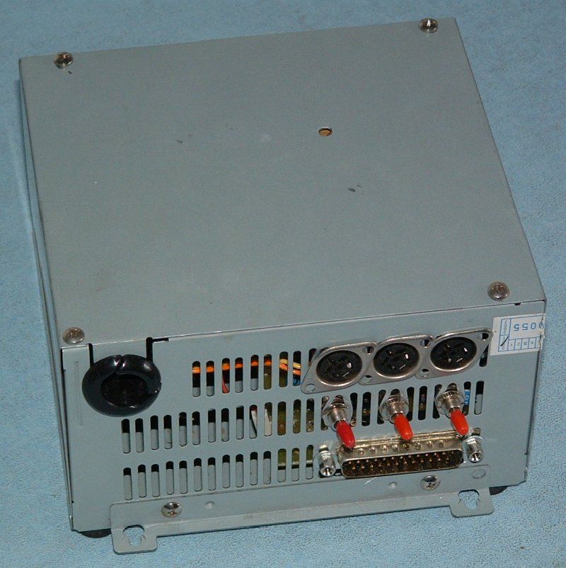
And please find the ensemble
installed in a former PC power supply box.
Economic, ultra-compact, perfectly shielded and very well cooled (with the
original power supply fan).
Switches control power of each board (That shut stepper power supply).